We have released a USB-C power delivery board that can sink up to 65W(hardware) and 100W(I2C configuration).

The Power Delivery Board is nothing but a sink controller board. It negotiates with the USB PD Charger and gets the desired voltage and current rating as per the desired configuration.
The USB-C PD Power Delivery Board could be used in various applications where you want to use USB-C to power your product or project.
USB-C PD Power Delivery Board provides a very easy-to-use DIP switch to select which voltage or current rating you need O/P from your USB PD Charger.
It also has an on-board DC-DC converter, which can generate either 5V or 3.3V based on the shorted jumper. It can easily provide you with around 3.3W. NOTE: Even more power could be taken from the DC-DC Converter if the USB PD voltage is lower(9V, 12V, etc.) or if you use an external heatsink.
Voltage, current selection, or monitoring is possible with the I2C interface provided on the 4-Pin header.
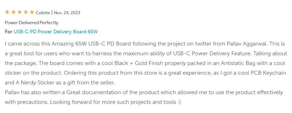
Customer’s Feedback about our USB-C Power Delivery Board
(Check the review on the Tindie Store)

USB-C PD Board Features:
- Made in India: Designed and Manufactured in India
- Compact Size: 50mm x 35mm
- USB-C Input
- Power delivery up to 65W via DIP switch and 100W via I2C command (I2C pullups are not on the board). Please note that the 3.25A setting(via DIP Switch) may not work with many USB-C PD chargers. We have also observed this during testing.
- An additional DC-DC Converter(TPS54302) is onboard to generate 3.3V 1A / 5V 0.65A output so that you need fewer components on your application board.
- 4x Mounting holes for easy mounting
- LED indication for USB-C Input, USB PD Output and DC-DC Converter Output.
- A 2-pin power terminal is provided for easy connection.
- A 4-pin 2.54mm header connector is provided for the I2C connection.
- Both connectors will come unsoldered.
High-Level Block Diagram

USB-C Power Delivery Board Images


USB-C Power Delivery Board Thermal Testing Images
We put a 60W (20V@3A load) on the board for two hours at room temperature(26 degrees C) and did not see even a 10-degree rise in the temperature. So, the board is quite stable.


DC-DC Converter Output Selection
By default, the 3.3V jumper will be shorted.
If you need 5.0V output, please open the 3.3V jumper pads and short the 5.0V pads. See the image below for the position of the pads.


DIP Switch Selection
Please note: On the Disp Switch, as you see on the board, the latch-up is ON, and the latch-down is OFF.
Please Note: Your USB-C PD Charger may not support all voltage or current settings. Please check your charger to see which settings are supported, and then set the DIP Switches accordingly. Otherwise, you may think the USB-C Power Delivery Board is not working. One example is shown below.

| Voltage Configuration | Switch Position |
|---|---|
| 5V O/P | S1 – 1 ON, S1 – 2, 3, 4 – OFF, S2-1 OFF |
| 9V O/P | S1 – 2 ON, S1 – 1, 3, 4 – OFF, S2-1 OFF |
| 12V O/P | S1 – 3 ON, S1 – 1, 2, 4 – OFF, S2-1 OFF |
| 15V O/P | S1 – 4 ON, S1 – 1, 2, 3 – OFF, S2-1 OFF |
| 18V O/P | S1 – 1, 2, 3, 4 – OFF, S2-1 ON |
| 20V O/P | S1 – 1, 2, 3, 4 – OFF, S2-1 OFF |
| Current Configuration | Switch Position |
|---|---|
| 1.5A O/P | S2-2 ON, S2-3, 4 – OFF |
| 2.0A O/P | S2-3 ON, S2-2, 4 – OFF |
| 3.0A O/P | S2-4 ON, S2-2, 3 – OFF |
| 3.25A O/P | S2-2, 3, 4 OFF |
How to configure/monitor via I2C
For I2C, you need to connect the USB PD board with your external MCU board using the I2C interface (SCL, SDA, GND). Please note the pull-up resistance is not present on the USB PD Board.
Register Mapping is given in the PDF below.
From where to buy it, and what is the cost?
USB-C PD Power Delivery Board is now available in online stores.


